
Virtuoso Guide
This is a guide for running simulations on virtuoso.
PREPARATION
- Prepare simulation and synthesis results.
- Modify the netlist file generated by synthesis tool, whose path is
workdir/syn/module_name/module_name.v.
a. Add the VDD and VSS ports, which should be inout type to every module.

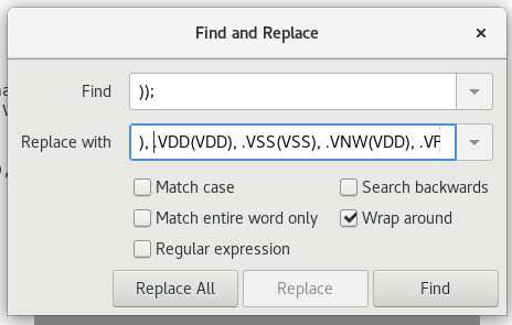
b. Use replace tool to modify every cell’s port, add .VDD(VDD), .VSS(VSS), .VNW(VDD), .VPW(VSS).
CREATE NEW FILES
-
Run virituoso in the virtuoso directory.
cd virtuoso/ virtuoso & -
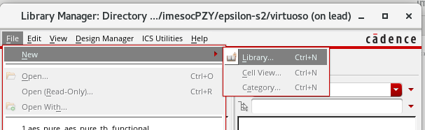
In library manager, File -> New -> Library -> New Library ->
Name:lib_namePath:$ProjectPath/virtuoso/-> OK.
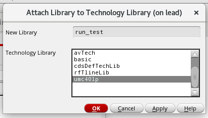
- Attach to existing library ->
lib_name-> OK.
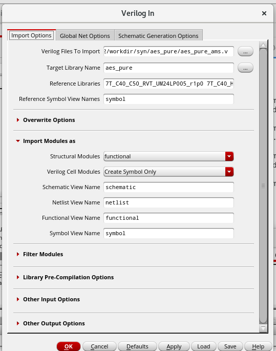
- In log window, File -> import -> verilog ->
netlist file-> OK. The Reference Library should be copied form the name in library manager. Other parameter is shown in the following figure.
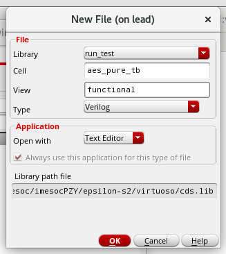
- In library manager, File -> new -> cellview ->
Name:lib_tbViwe:functionalType:Verilog-> OK.
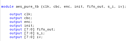
- In popup text editor, paste the testbench without tested module, also add output port to the testbench.
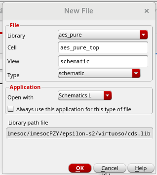
- In library manager, File -> new -> cellview ->
Name:lib_topView:schematic-> OK.
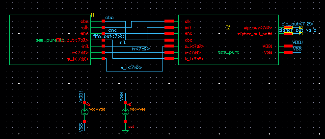
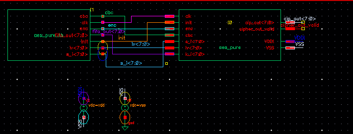
- Display the schematic of the tested module, and add the testbench to the schematic
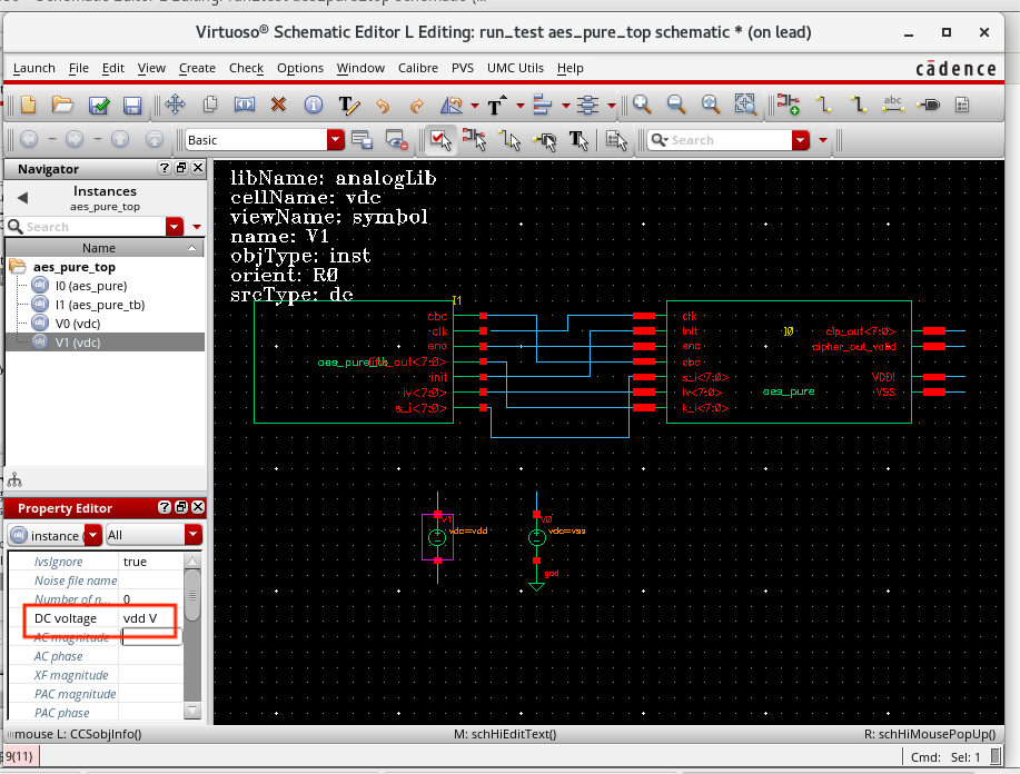
a. Add the instances, source and ground. Also, connect the ports. Instances source and ground can by created by Create -> Instance. The source and ground can be found in the
analogLiblibrary.
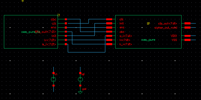
b. Give the voltage to the sources. Select the source, right click, and modify theDC Valuein the Property Editor, the value should bevddandvss.
c. Presslin the keyboard to add the label to the signals. Then clickcheck and save.
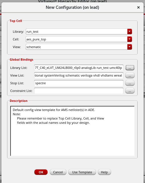
- In library manager, File -> new -> cellview ->
Name:lib_topView:config-> OK.
a. In popup window,
View:schematic, use templateARM. Then, select theLibrary List, which should include own library and the library which is needed -> OK.
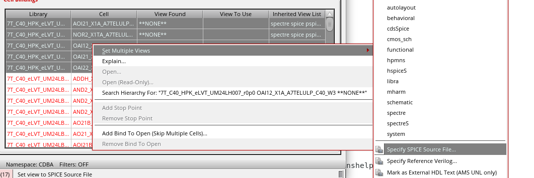
b. Select the cells in red, rignht click -> Set Multiple Views -> Specify SPICE Source File ->Corresponding.cdlfile -> OK. The.cdlfile should be found in the/cad/tech/directory. Then, clickRecompute the hierarchy-> OK.
SET SIMULATION
- Click ADE Explorer -> Create New View to get the maestro cell view.
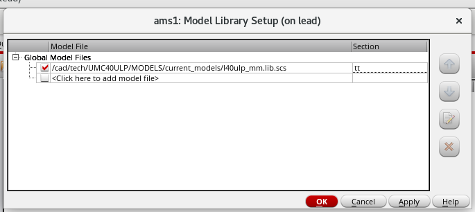
a. Setup -> Model Library. Select the
.scsfile in the/cad/tech/directory, section should bett.
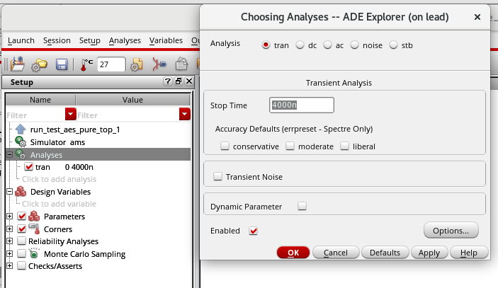
b. Double click the Analyses to set stop time.
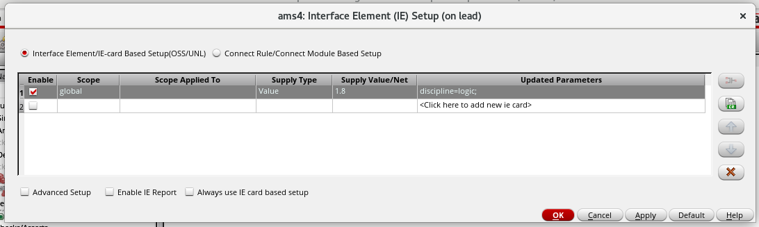
c. Setup -> Connect Rules.
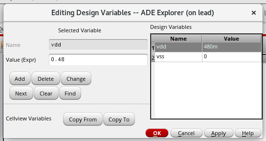
d. Double click the Disign Variables, click Copy From to set thevddandvssvalue.
e. Outputs -> TO Be Plotted -> Select On Design -> Select the output signals. Note that the sources should be selected, too.
RUN
- Run the simulation.
- If there is some error, check the log window. Open the functional view of corresponding cell, and click Bulid a database -> replace. Then, check the lib_top schematic. After that, run the simulation again.